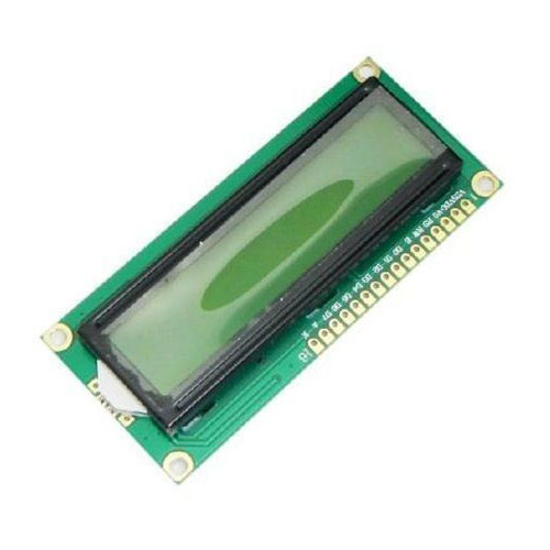
16x2 LCD DISPLAY INTERFACING WITH NODEMCU
In this experiment, we are going to interface 16×2 LCD display to NodeMCU and going to connect 16×2 LCD display in a four-bit mode and we can print the data or message on our LCD screen with the help of NodeMCU board.
Synopsis

In this experiment, we are going to interface 16×2 LCD display to NodeMCU and going to connect 16×2 LCD display in a four-bit mode and we can print the data or message on our LCD screen with the help of NodeMCU board.

Description


16x2 LCD :

The Data pins from D0 to D7 forms an 8-bit data. These data pins are connected to Microcontroller to send 8-bit data. These LCD’s can also operate on 4-bit mode in such case the Data pin 4,5,6 and 7 will be left free.

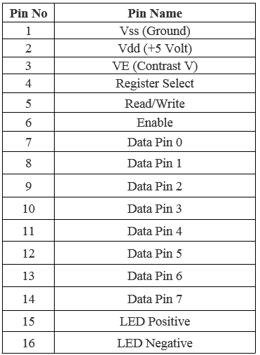
Pin Configuration of 16x2 LCD
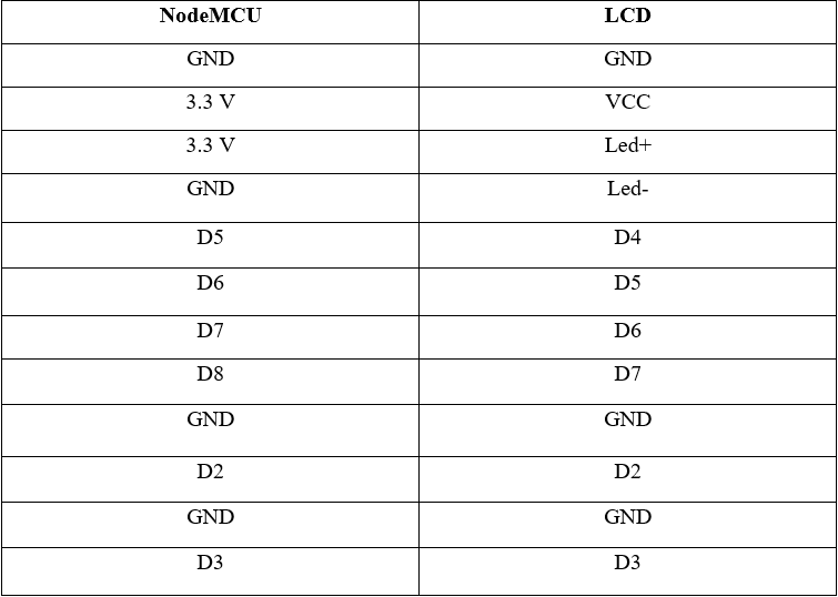

NodeMCU

A NodeMCU is a development board with an inbuilt Wi-Fi module in it. It is a basic and a cheapest board to carry out projects using internet of things. The NodeMCU has ESP8266 microcontroller unit in it. The operation of this microcontroller is controlled with the programs used in Arduino thus making it very easier to use and also to learn basic IoT projects. This board has inbuilt 2.4GHz antenna to receive Wi-Fi functions. This board has a memory of 4mb to store the data acting as ROM and 64Kb of RAM. This board operates at 3.3 volts and 5v and it is mandatory to operate the board at these voltage levels and if voltage is more than that it will board may damage few GPIO pins (general input-output pins).


Pin Configuration

1. Vin: 3.3V can be provided at this pin as the supply to power on the board. This pin is used to power on the entire microcontroller.

2. GND: This pin is connected to the negative terminal of the battery.

3. RST: This pin resets the microcontroller and clears the memory.

4. EN: This pin is used to enable the operation of microcontroller.

5. 3V3: This pin provides 3V output and this can be used to power up some sensor units connected to the microcontroller.

6. SD1, CMD, SD0, CLK: These pins are used in SPI communication, that is it is used to transfer the signals between two microcontrollers, Rx and Tx modules with asynchronous transmission.

7. SD3, SD2: These pins can also function as asynchronous transmission or as GPIO pins.

8. RSV: These are two reserved pins used by the microcontroller and cannot be used in connecting any external circuits to it.

9. A0: This microcontroller only has one analog pin for Analog communication. This A0 pin is used in analog signal communication.

10. GPIO 1 – 16: This controller board has 16 input-output pins which be used as input or output pin based on the programming.

11. GP10 1, 3, 13, 15: This microcontroller has 2 UART communication pins, RX0, TX0 (GPIO 1 & GPIO 3) and RX1, TX1 (GPIO 13, GPIO15).

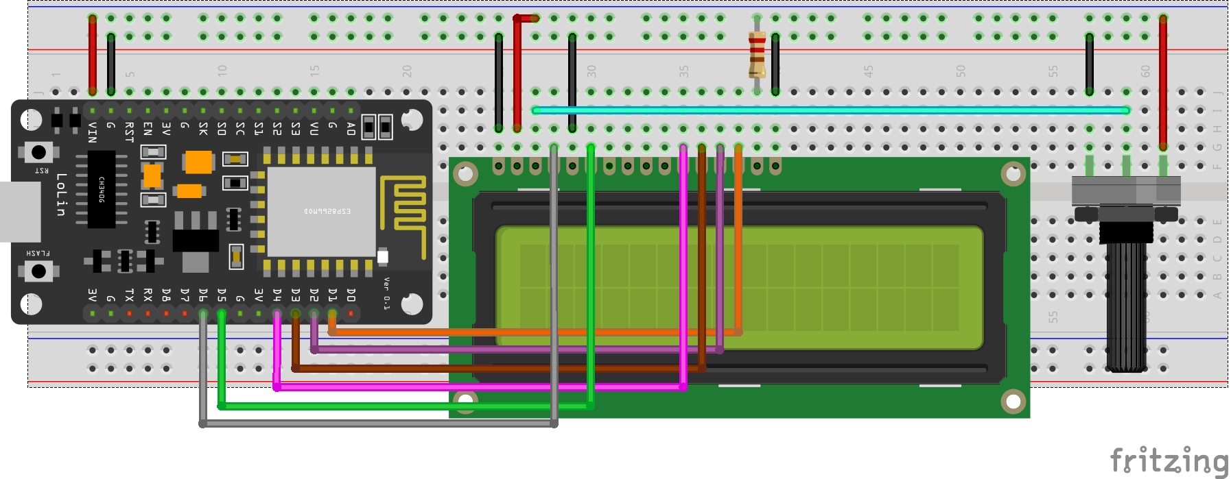
16x2 LCD display and NodeMCU pin connections


Schematic


Code

#include <LiquidCrystal.h>

const int rs = D6, en = D5, d4 = D4, d5 = D3, d6 = D2, d7 = D1;
LiquidCrystal lcd(rs, en, d4, d5, d6, d7);

void setup() {
  lcd.begin(16, 2);
  lcd.print("   WELCOME TO   ");
  lcd.setCursor(1,0);
  lcd.print("    GEMLABS    ");
}

void loop() {
  
}

Error message here!

Show Error message here!


Forgot your password?

Error message here!

Send OTP

Error message here!

Show Error message here!


Lost your password? Please enter your email address. You will receive a password you Need.

Send Error message here!


Back to log-in

Close